The representation of linear components and circuits in the frequency domain using S-parameters is a common industry standard in radio frequency engineering. S-parameters describe the ratio between an incoming wave A and a reflected wave B without considering the actual power waves of the circuit. This makes them very attractive for the description of simple linear behavioral models for a given frequency. However, real non-linear effects of components (e.g. the IP3 in amplifier circuits) cannot be modelled satisfactorily in this way, because higher harmonics are involved here. The effects of non-linear distortion are displayed here
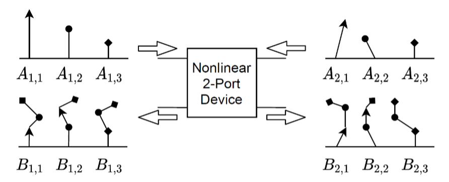
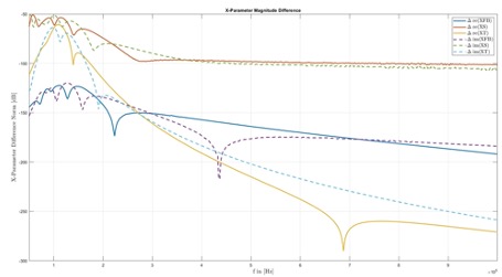
Therefore, some time ago Agilent introduced a new standard referred to as X-parameters, which models the influences of harmonic distortion at the input for pre-defined harmonics. The extraction of these so-called X-parameter models can be done in several different ways. Already functional components can be measured very efficiently with an NVNA (non-linear vector network analyzer). Alternatively, existing and sufficiently accurate component models may be utilized. The Cadence AWR Design Environment provides tools to generate X-Parameters from such behavioral models. In the course of this project, the basic functionality of those tools is reverse-engineered and compared to a verified alternative approach which utilizes perturbation techniques within the LinzFrame device simulator. Additionally, a MATLAB toolbox has been created so simplify the import and export of X-Parameter files with the industry standard file format XnP. The results for a simple common emitter amplifier are displayed below. The X-Parameter differences for the respective components (X_{fb}, X_{S} and X_{T}) are basically non-existent when comparing the AWR tool set with the verified LinzFrame algorithm.